
28 Jul Gear Quality Control Inspection Process
Gear Quality Control Introduction
Australian businesses design and manufacture gears of various sizes and tolerance requirements for industries including automotive, transportation, power generation and more. Traditionally, gears are inspected using manual gauges or CMMs. Gauges and manual tools tend to be prone to human error as well as being highly inaccurate and not allowing for automated digitisation of results and reports. Although highly accurate, CMMs represent heavy capital investments as well as providing slow and limited, point-based measurement results.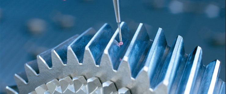
 By using optical metrology systems, gear inspection can be sped up while maintaining a high degree of accuracy and providing data on the whole part instead of individual points as a CMM would. Furthermore, optical systems offer many benefits for large scale objects as you will see below.
Gear 3D Inspection Tools & Processes
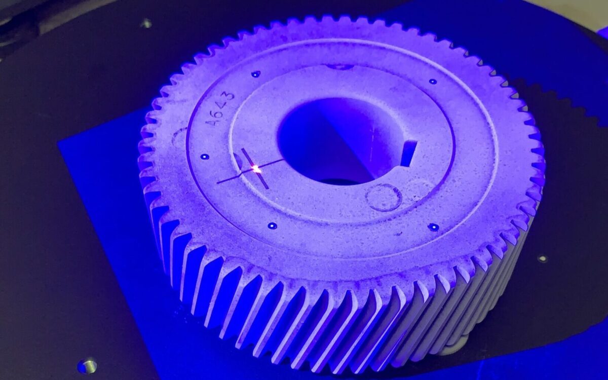
The video bellow highlights the gear quality control inspection process from start to finish. Step 1: part preparation using AESUB Scanning Spray Step 2: 3D scanning using the ATOS Q optical sensor & GOM Rotary table for automation Step 3: GOM Inspect was used to render mesh data and perform inspection and analysesGear Quality Control Results
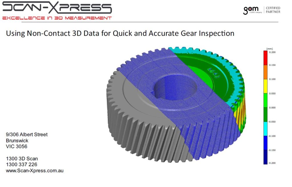
Many key parameters can be analysed directly in the software allowing operators to quickly spot defects and perform quality check. Reports can be automatically created for client quality assurance and traceability purposes. Complete the form below to download a copy of the report:
Benefits of Optical Metrology
The gear 3D inspection process as shown in the video – from part preparation to scanning and obtaining full 3D mesh data – took less than 8 minutes. This time can be reduced further by pre-automating the inspection passes and using jigs. A CMM performing this task would be providing only partial data points, not full-field data, in double the time. These benefits are compounded as the gear size increases. For large gears, a CMM or manual gauge inspection would require a highly costly machine or jig which would allow the operator to move across the entire surface. Even then, the data would be highly unreliable as the accumulative errors of each measurement point would not be actively tracked by the system. An optical system could capture the data with the help of a simple tripod or robotic arm if automation is desired. Optical metrology also uses active photogrammetry systems – such as the TRITOP – for measuring large objects. By taking a few photos of position markers placed around the gear, the system creates a reference environment upon which each scan is mapped. This ensures that the data points captured by the scanning system are perfectly aligned to each other essentially eliminating compounded errors.
Interested in reading about our next projects and company news?
Subscribe