
10 Mar Defence 3D scanning & Reverse Engineering
BAE Systems Project Requirements
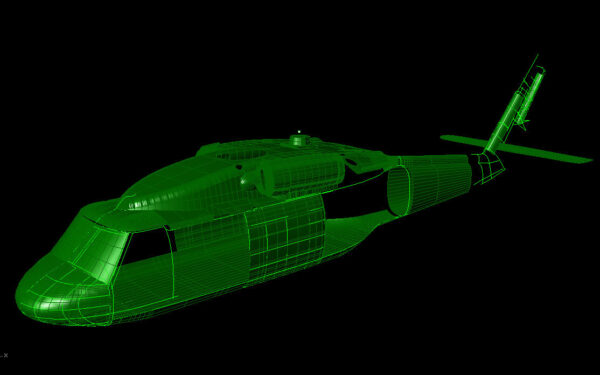
The requirements for the project were a CAD data file within a verifiable accuracy of 0.1 mm of the complete exterior of the aircraft as well as certain internal areas of interest. The external and internal data had to be integrated within the same coordinate frame work to simply design tasks. In order to achieve this, we selected to use the GOM TRITOP photogrammetry system to establish a working reference frame for our scan data and ensure accuracy. We then used a GOM ATOS optical sensor to capture accurate data.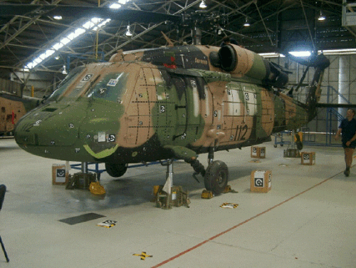
Metrology Methodology & 3D Scan Results
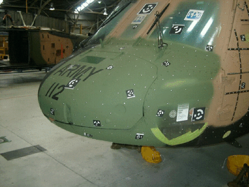
The TRITOP system takes high resolution two-dimensional pictures of objects to provide an accurate large scale 3D co-ordinate framework based on digital photogrammetry techniques. Coded and un-coded markers were applied across the surface of the helicopter and multiple images were captured by the photogrammetry camera. Using these images, we are able to create an accurate frame of reference points for the rest of the data capture and eventual CAD creation. In order to capture an accurate digital twin of the helicopter, we used a GOM ATOS white light optical metrology system. A total of 41 3D scans were collected across the surface of the aircraft containing over 12 million data points and allowing us to achieve a verifiable 0.1 mm accuracy. The digital twin of the aircraft is created in GOM software as a polygon mesh. Using a combination of reverse engineering software packages and techniques*, the STL data is used to create CAD data by best fitting CAD elements into the captured mesh. *Note this project was performed in 2008 when reverse engineering and CAD was much less advanced than it is today. Now, it is possible to automatically reverse engineer complex objects and surface captured using 3D scanning with software tools such as Geomagic Design X or ZEISS Reverse Engineering.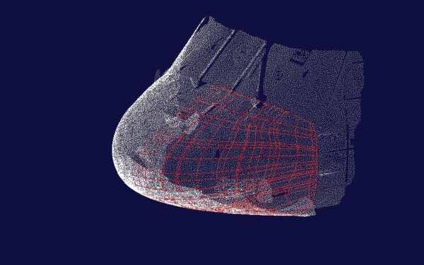
Interested in reading about our next projects and company news?
Subscribe